Syed Jahanzaib – Personal Blog to Share Knowledge !

November 27, 2013

DVR/CCTV & Browser Compatibility issue

Filed under: General IT Related — Tags: , , , , , — Syed Jahanzaib / Pinochio~:) @ 1:19 PM

From past few weeks we were having issues accessing our DVR systems from the Internet. The problem was that only when authentication dialogue appears, and after entering credentials , nothing appears further , no video nothing else, seems like connection going in sink hole.

As showed in the images below . . .

Login screen appear but with no background or complete logo

cctv1.

But after entering credentials, no video or any thing else came except for blank screen or with no video.

cctv2


First we thought it might be something with the port forwarding , so first we did some investigation and found nothing, so called a Cisco Support personnel, and he also did some checking and found nothing.

Then we suspect our ISP and lounged complain regarding possible content filtering, but they claimed none of any traffic is filtered in corporate networks except VOIP.

We called the DVR support team and they claimed everything is fine at there DVR systems (nooobs :p)
Later on I configured an Mikrotik Routerboard in parallel just to verify that nothing is wrong  with the Cisco ASA firewall.

After searching on Google, I found out that it is something related to browser compatibility issues with the ACTIVEX component of the DVR manufacturer. But I was unable to sort it out completely. Luckily a friend from PORTUGAL (Mr. Rui Oliveria) confirmed me about the browser compatibility issue, and recommended me to run Browser (Internet Explorer 10) in IE9 mode. and ALHAMDOLILLAH it worked without any issue.

As showed in the image below . . .

cctv3-final.

.

Alternate way to launch Internet Explorer 10 in IE-9 mode via shortcut

To launch Internet Explorer 10 in IE9 mode, create a HTML file (you can use simple ntoepad to copy paste following code, and save it with IE9.html )

Copy paste the code from following pastebin location (WordPress is not good with pasting html codes)

http://pastebin.com/Uw9N9h94

Now double click this file and IE10 will be launch in IE9 mode. You can modify it as per your requirements.

.

You can use IETAB for Google Chrome & Firefox to view the DVR system.

.

Regard’s
Syed Jahanzaib


November 25, 2013

Mikrotik Central VPN Server For Remote Branches Connectivity

Filed under: General IT Related, Mikrotik Related — Tags: , , — Syed Jahanzaib / Pinochio~:) @ 1:54 PM


mini-isp.

vpn connectivity

Consider following scenario:

An ISP have multiple locations all over the country. Main Mikrotik router at NOC have fixed public IP. Radius Billing system is connected with LAN. All remote locations have Mikrotik Router boards as NAS and have dynamic public IP. All locations have there own internet connectivity with various ISP’s but we want to use our main RADIUS server as a centralized billing solution for all the REMOTE locations. So this is a short guide on howto create central Radius Server and connected all remote branches/nases with it.


Basic Points:

Create PPTP server at your Head Office Mikrotik.
Create user account in secret section, nd assign him fix IP address like 172.16.1.50
Now at branch office, create a pptp client in mikrotik pptp section, and add head office IP / user id passwd, Dont forget to UNCHECK “add DEFAULT ROUTE” button. because if you do so it will override default route and will route every traffic including internet requests too to head office, which will overload head office internet connection, since we only want to route request for specific IP/subnet, so we will create a route at both end so that request for specific ip subent should go via vpn tunnel .

Head Office Mikrotik Config

LAN subnet = 10.0.0.1/8
WAN subnet = 1.1.1.1/29
Radius = 10.0.0.2/8

First add IP pool for VPN users, like same as LAN series but with specific series.

/ip pool
add name=PPP-Pool ranges=172.16.0.1-172.16.1.255

Now add VPN Profile

/ppp profile
set 0 change-tcp-mss=yes name=default only-one=default use-compression=default use-encryption=default use-mpls=default use-vj-compression=default
add change-tcp-mss=default dns-server=10.0.0.1 local-address=10.0.0.1 name=vpn-profile only-one=default remote-address=PPP-Pool \
use-compression=default use-encryption=default use-mpls=default use-vj-compression=default
set 2 change-tcp-mss=yes name=default-encryption only-one=default use-compression=default use-encryption=yes use-mpls=default use-vj-compression=default

Now enable VPN server

/interface pptp-server server
set authentication=mschap1,mschap2 default-profile=default-encryption enabled=yes keepalive-timeout=30 max-mru=1460 max-mtu=1460 mrru=disabled

Now add user so that we will be testing from remote location NAS.

/ppp secret
add caller-id=”” disabled=no limit-bytes-in=0 limit-bytes-out=0 name=aa password=aa profile=vpn-profile routes=”” service=any

Now add route for the 192.168.100.0/224 subnet in IP ROUTE section , via pptp gateway.

Remote Branch Mikrotik Config

LAN subnet = 192.168.100.1/8
WAN subnet = DYNAMIC Public IP x.x.x.x

Now we want to connect remote NAS with head office VPN server so that it can use central radius server as a centralized billing system.

In short: Create a pptp dialer , pointing to Head Office Main RB (where vpn is configured) , enter valid user id password, Make sure you remove tick from add default route, after its connect, simply add a route for 10.0.0.0/8 and its gateway pointing to pptp-out1 (pptp link we created above)

To be continued . . . will write soon about it , while writing guide,an issue in the network popedup . . 00-(

[Mikrotik Hotspot] Workaround to move Static Queue above Dynamic Queue

Filed under: Mikrotik Related, Uncategorized — Tags: , — Syed Jahanzaib / Pinochio~:) @ 10:37 AM

Scenario:


We have HOTSPOT configured in Mikrotik Routerboard along with SQUID proxy server. Users management is done in ser Manager which creates dynamic queue upon each user login. We have created one simple queue that allows SQUID cache marked packets unlimited speed so that user should get cache at unlimited rate bypassing the internet queue user have. The issue was that when any hotspot user user login and Hotspot/Radius creates Dynamic Queues, and it override our created simple queue of cache by moving itself above the static queue, so the cache-hit queue remain useless to provide unlimited speed to cache packets due to its lower position as things works order wise in the Mikrotik.

As showed in the image below . . .

Before HOTSPOT user login,

cache-1


After HOTSPOT user logged in,

cache-2

The workaround for this issue was to add a simple command in the HOTSPOT user profile login section which will moves this static queue name “cache-hit” to 0 (top number) whenever any user login.

The command/script can be added in HOTSPOT > USERS PROFILES > SCRIPTS > On Login section. This way whenever any hotspot user login, this command/script will run, and it will move the cache-hit to 0 number (Top)

Ok first rename your cache hit queue to “cache-hit

Now add cmd/script in HOTSPOT > USERS PROFILES > SCRIPTS > On Login section that will move the cache-hit queue to top. (in this example I have only one default profile, if you have multiple user profiles, you have to add this in all profiles either via CLI, or preferably via GUI )

To move queue based on packet-marks name, use following

/queue simple move [find packet-marks="cache-hit"] 0]

OR to move queue by finding Comments of the queue use following

/queue simple move [find comment ="cache-hit"] 0


Another command format

 /queue simple move [find name="cache-hit"] [:pick [find] 0] 


After adding this cmd, whenever any hotspot user will login , the hotspot profile will execute this cmd & it will move the cache-hit queue to TOP.

Now the results will be as showed in the images below . . .

cache-final


Some TIPS

Move queue before another queue name ‘ZAIB’
/queue simple move [find packet-marks=”YOUTUBE”] destination=ZAIB

To specific Number, like move this queue on number X
/queue simple move [find packet-marks=”YOUTUBE”] [:pick [find] 3]

Move to TOP
/queue simple move [find packet-marks=”YOUTUBE”] 0]

Move Queue by finding its comment

/queue simple move [find comment =”YOUTUBE”] 0

How to remove all dynamic queues [can be used in script login section]

/queue simple remove [find where dynamic]


Regard’s
Syed Jahanzaib

[Lotus Notes] INBOX not showing any mails, but appearing in ALL DOCUMENTS folder

Filed under: IBM Related — Tags: , — Syed Jahanzaib / Pinochio~:) @ 9:06 AM

lotusToday morning, When one of our user opened Lotus Notes client, no email was showing in INBOX, but all appearing in ALL DOCUMENTS folder. To fix this I issued following command and problem went away and INBOX showed all emails.

load updall -r mail\usermailfile.nsf

This problem also occurs if you have corrupted INBXO view , dual of them. To check this you ahve to open user mail file in Domino Designer, and lookfor two inbox view. If there are two inbox view, first create a temporary folder, and move all the inbox mails to this temp folder, now create both inbxo folder, and replace design, this will create inbox view, now move all mails from temp folder to inbox , simple is that :p

Tip: If the problem remains still, then try to replace the FOLDER DESIGN.

Also read this thread, it really have some very good information to solve this problem.

http://community.spiceworks.com/topic/231092-lotus-notes-no-emails-showing-up-in-inbox-but-are-in-all-documents-folder
http://www-01.ibm.com/support/docview.wss?uid=swg21093841

Regard’s
Syed Jahanzaib

November 23, 2013

FUN with Mikrotik BRIDGE Series# Filter PPPoE Requests – Part#1 

Filed under: Mikrotik Related — Tags: , , , — Syed Jahanzaib / Pinochio~:) @ 11:22 PM

Part #1 : FUN with Mikrotik BRIDGE Series# Filter PPPoE Requests – Part#1 < You are Here
Part #2 : FUN with Mikrotik BRIDGE Series# Redirecting Traffic with Mikrotik Bridge


Disclaimer! This is important!

Every Network is different , so one solution cannot be fit/applied to all. Therefore try to understand logics & create or modify the solutions as per your network scenario. Never follow copy paste blindly.

My humble request is that kindly donot consider me as an expert on this stuff, I am NOT certified in anything Mikrotik/Cisco/Linux or Windows. However I have worked with some core networks and I read , research & try stuff all of the time. So I am not speaking/posting about stuff I am formerly trained in, I pretty much go with experience and what I have learned on my own. And , If I don’t know something then I read & learn all about it.

So , please don’t hold me/my-postings to be always 100 percent correct. I make mistakes just like everybody else. However – I do my best, learn from my mistakes and try to share tips that worked for me.

Regard’s
Syed Jahanzaib~


If you are running a network or ISP/WISP, and using Mikrotik as a PPPoE server, then you may have ran into this problem that many users have configured wifi router at there home to share internet between mobile/laptop and other devices, its common now a days. Usually PPPoE dialer is configured in user WiFi ROUTER. But the problem begins that if the user account gets expired BUT the router will keep retrying PPPoE dialer again n again 24 hours a day , and imagine if you have lots of routers doing this sort of flooding/bombing, you will see only PPPoE failed authentication messages in Mikrotik logs and you wont be able to see any other valid info due-to continuous logging of failed auth messages. You can ignore it if the number is low, but some times it becomes annoying to see such messages, and also if you are very short in space with lower model of RB, then it will gonna become issue for you. Some times its not just possible to visit at user end to tell him that turn off his router / remove his cable from the switch , OR if you are running layer2 un managed switches, OR you simply don’t want to visit that user. After little searching (did not made extensive search) I found out that from Mikrotik Firewall , you cannot block PPPoE request as it works on BROADCAST.

So I found the following method to block PPPoE request from particular VALID expired users. ( I am using the word VALID expired users, because if the user is not doing it intentionally then its easier to block him at mikrotik level, but if any smart bugger is doing it just to annoy you, you have to hunt him down and cut the cable or block at manageable AP level, because he can change the mac address any time)

Ok the simple theory is ,

1-  Create bridge interface,
2-  Enable bridge firewall,
3-  Add your LAN interface in it,
4-  Finally create a filter that blocks PPPoE discovery for that specific MAC address 🙂 and that’s it 🙂

Ok here we go . . .

We will first add virtual BRIDGE interface

/interface bridge
add admin-mac=00:00:00:00:00:00 ageing-time=5m arp=enabled auto-mac=yes disabled=no forward-delay=\
15s l2mtu=65535 max-message-age=20s mtu=1500 name=bridge1 priority=0x8000 protocol-mode=none \
transmit-hold-count=6

Now we will add LAN interface in this BRIDGE to intercept every traffic passing from it and block it before it passes to LAN interface

/interface bridge port
add bridge=bridge1 disabled=no edge=auto external-fdb=auto horizon=none interface=LAN-ether2 \
path-cost=10 point-to-point=auto priority=0x80

Now we will enable BRIDGE FIREWALL, it is necessary as mikrotik IP/FIREWALL will not be applicable to filter traffic in BRIDGE interface.

/interface bridge settings
set use-ip-firewall=yes use-ip-firewall-for-pppoe=yes use-ip-firewall-for-vlan=no

Finally we will create BRIDGE FILTER(s) to drop traffic from particular user to block PPPoE connection attempts only, using his mac address.

/interface bridge filter
add action=drop chain=input comment=\
"Block only PPPoE Discovery (connectivity) from user 'ZAIB' to prevent pppoe flooding" disabled=no \
mac-protocol=pppoe-discovery src-mac-address=00:23:AE:A8:1F:7F/FF:FF:FF:FF:FF:FF

If you want to BLOCK ANY traffic coming from that or other user mac address to pass from bridge to LAN interface. (some times is a good approach 😉 hmmmmm )

## IF you want to BLOCK ANY traffic coming from that or other&nbsp; user
#add action=drop chain=input comment="Block ANY traffic from user 'KARACHI'" disabled=yes \
#&nbsp;&nbsp;&nbsp; mac-protocol=ip src-mac-address=00:23:AE:A8:1F:7F/FF:FF:FF:FF:FF:FF

As shown in the image below . . .

birdge-

pppoe-1


ote: I found this method with some R&D using WIRESHARK capturing tool but I am very confident that there could be suitable methods that maybe more simple and easier to implement with simple rules, If you have info, drop me a message so that I can update these little notes.


Regard’s
Syed Jahanzaib

November 13, 2013

Mikrotik with Multiple WAN IP’s and Port Forwarding / HAIRPIN NAT

Filed under: Mikrotik Related — Tags: , , , , — Syed Jahanzaib / Pinochio~:) @ 12:09 PM

CISCO-asa-replacement-diagram

Mark my words !

MIKROTIK is the Future & Cisco’s Domination will go down day by day.  For sure CISCO still holds the majority of shares in the router/switching world, but it will going to change very soon  . . .
CISCO is the best, but at a higher price. Cisco have edge dueto its reliable OS and Hardware.
On the other hand Mikrotik is good for multi purpose requirements in a very cheap price as compared to CISCO.  So very cost effective solution.

Its all about personnel preference, choice, budget. But even if i have high budgeting, I will prefer Mikrotik 🙂 , buts that’s my personnel choice. and you are not bound to agree with it 😀
Jz

Recently I did some testing at my office for a possible replacement of Cisco ASA 5510 Firewall/Router with Mikrotik Router-board. Following are some short reference on how I did it. I had a /29 public ip pool.  Configuration was was pretty straight forward but i was confused on howto route specific LAN server (or ip) traffic with Specific WAN ip. Using src-address I managed to solve it. Following are short reference for future usage.

Scenario is as follows

We will configure all useable WAN ip addresses in mikrotik wan interface, and we will forward required ports from specific wan ip’s to specific lan servers. we will also configure firewall so that only required ports are open from WAN side for security purposes, all other traffic will be denied on WAN interface. We will also bind local servers with specific WAN ip addresses.

Mikrotik have two interfaces.

ether1 = LAN users
ether2 = WAN Link

Now we want to forward traffic as follows. (all ip scheme used here is fictional and for example purposes only)

mail server = 10.0.0.2 → 1.2.3.1    WAN IP
dude server = 10.0.0.3 → 1.2.3.2   WAN IP
cctv1 server = 10.0.0.4 → 1.2.3.3   WAN IP
cctv2 server = 10.0.0.5 → 1.2.3.4   WAN IP

IP Configuration at Mikrotik Interfaces . . .

/ip address
add address=10.0.0.1/8 comment=LAN disabled=no interface="LAN - ether1"
add address=1.2.3.1/29 interface="WAN - ether2"
add address=1.2.3.2/29 interface="WAN - ether2"
add address=1.2.3.3/29 interface="WAN - ether2"
add address=1.2.3.4/29 interface="WAN - ether2"

Filter Rules Section to allow only required Incoming traffic on WAN interface, and DENY all other for security purposes 🙂

Now we will first add required ports in firewall filter BEFORE DENY rule which is in last.


/ip firewall filter
add action=accept chain=input comment="SMTP" disabled=no dst-address=1.2.3.1 dst-port=25 in-interface="WAN - ether2" protocol=tcp
add action=accept chain=input comment="POP3" disabled=no dst-address=1.2.3.1 dst-port=110 in-interface="WAN - ether2" protocol=tcp
add action=accept chain=input comment="Webmail" disabled=no dst-address=1.2.3.1 dst-port=80 in-interface="WAN - ether2" protocol=tcp
add action=accept chain=input comment="DUDE" disabled=no dst-address=1.2.3.2 dst-port=80 in-interface="WAN - ether2" protocol=tcp
add action=accept chain=input comment="CCTV 1" disabled=no dst-address=1.2.3.3 dst-port=81 in-interface="WAN - ether2" protocol=tcp
add action=accept chain=input comment="CCTV 2" disabled=no dst-address=1.2.3.4 dst-port=82 in-interface="WAN - ether2" protocol=tcp
add action=accept chain=input comment="WINBOX 8192" disabled=no dst-port=8192 in-interface="WAN - ether2" protocol=tcp
add action=accept chain=input comment="Allow PING ICMP " disabled=no protocol=icmp
add action=drop chain=input comment="DROP ALL INCOMING TRAFFIC ON WAN INTERFACE" disabled=no in-interface="WAN - ether2"

NAT Section To Do Port Forwarding From WAN ip’s  To  Local Server’s and use src-nat to bind local server to route traffic via specific WAN IP

### First dst-nat section to forward port


/ip firewall nat
add action=dst-nat chain=dstnat comment="SMTP 25 Forward to MAIL-Server" disabled=no dst-address=1.2.3.1 dst-port=25 in-interface="WAN - ether2" protocol=tcp to-addresses=10.0.0.2 to-ports=25
add action=dst-nat chain=dstnat comment="POP3 110 Forward to MAIL-Server" disabled=no dst-address=1.2.3.1 dst-port=110 in-interface="WAN - ether2" protocol=tcp to-addresses=10.0.0.2 to-ports=110
add action=dst-nat chain=dstnat comment="Web 80 Forward to MAIL-Server Webmail" disabled=no dst-address=1.2.3.1 dst-port=80 in-interface="WAN - ether2" protocol=tcp to-addresses=10.0.0.2 to-ports=80
add action=dst-nat chain=dstnat comment="Web 80 Forward to DUDE" disabled=no dst-address=1.2.3.2 dst-port=80 in-interface="WAN - ether2" protocol=tcp to-addresses=10.0.0.3 to-ports=80
add action=dst-nat chain=dstnat comment="CCTV1 - 81 Forward to cctv1" disabled=no dst-address=1.2.3.3 dst-port=81 in-interface="WAN - ether2" protocol=tcp to-addresses=10.0.0.4 to-ports=81
add action=dst-nat chain=dstnat comment="CCTV2 - 82 Forward to cctv2" disabled=no dst-address=1.2.3.4 dst-port=82 in-interface="WAN - ether2" protocol=tcp to-addresses=10.0.0.5 to-ports=82

### Now route specific local servers traffic from specific WAN IP address

add action=src-nat chain=srcnat comment="Rotue mail traffic via 1.2.3.1" disabled=no src-address=10.0.0.2 to-addresses=1.2.3.1
add action=src-nat chain=srcnat comment="Rotue DUDE traffic via 1.2.3.2" disabled=no src-address=10.0.0.3 to-addresses=1.2.3.2
add action=src-nat chain=srcnat comment="Rotue CCTV1  traffic via 1.2.3.3" disabled=no src-address=10.0.0.4 to-addresses=1.2.3.3
add action=src-nat chain=srcnat comment="Rotue CCTV2  traffic via 1.2.3.4" disabled=no src-address=10.0.0.5 to-addresses=1.2.3.4

add action=masquerade chain=srcnat comment="Default Masquerade Rule for LAN" disabled=no out-interface="WAN - ether2" src-address=10.0.0.2-10.0.0.255

Now test it from WAN side. You can check port status from http://www.yougetsignal.com/tools/open-ports/

♣ ♣ ♣

<<    HAIRPIN NAT   >>

Using above method, I was ablet o successfully setup a port forwarding on a Mikrotik router that do port forwarding from mikrotik wan ip to local lan servers (Example: 1.2.3.4:3389 to 192.168.1.10:3389)
BUT there is a BUT, when I tried to open Mikrotik WAN ip from local LAN user, for example

192.168.1.20    –>    1.2.3.4:3389    –>   192.168.1.10:3389

it didn’t opened and the connection goes in SINK hole, means lost.

The solution was to rewrite the port forwarding rule to NOT to use in-interface=WAN-GATEWAY, but dst-address-type=local
This is called – among other terms – hair pin NAT because the traffic flow has clients enter the router through the same interface it leaves through, which when drawn looks like a hair pin.
As showed in the example below . . .

# DST-NAT rule to redirect port 3389 from
/ip firewall nat
add action=dst-nat chain=dstnat disabled=no dst-address=1.2.3.4 dst-address-type=local dst-port=3389 protocol=tcp to-addresses=192.168.1.10 to-ports=3389 comment="Redirect RDP PORT  TCP 3389 to local server"

# Masquerade local traffic going to mikrotik WAN IP - [To access that service from LAN using mikrtoik wan ip]
/ip firewall nat
add chain=srcnat src-address=192.168.1.0/24 dst-address=192.168.1.10 protocol=tcp dst-port=3389 out-interface=LAN-Interface action=masquerade comment="Masquerade Traffic going to WAN IP of mikrotik from local LAN users"

Regard’s
Syed Jahanzaib

November 2, 2013

Mikrotik DUDE SMS Notification !

Filed under: Mikrotik Related — Tags: , , — Syed Jahanzaib / Pinochio~:) @ 7:25 PM

1- Send SMS from Windows base DUDE using Mikrotik attached GSM Modem

2- Send SMS from Windows base DUDE using Linux Base KANNEL SMS Gateway  [updated 10th Oct 2015]


SCENARIO # 1


1- Send SMS from Windows base DUDE using Mikrotik attached GSM Modem

Assumptions:

GSM device is connected with Mikrotik for SEND/RECEIVE purposes.

DUDE is installed in another windows base PC.

As far as my research goes, there is no direct method in Dude to send SMS using DUDE own mechanism, you must have to involve / call 3rd party tool to accomplish the sms sending task. It can be windows CLI base SMS sender program like smssender.exe/gammu for win32 , sms base HTTP gateway or whatever.

You can also connect gsm device to your windows base PC, but in my scenario, my gsm device was not supported in 64 bit version of Windows 7, that’s why I had to take a long route of sending sms via mikrotik, also my mikrotik is set to receive sms to to perform various function like reboot, wan status etc , so chill 🙂 )

Now the simple task is that we want to send DUDE notification via SMS using Mikrotik GSM/Mobile device, Just in case any critical device/server goes down.

We have to configure both Mirkotik server as well as DUDE too. so first Mikrotik section.

MIKROTIK Section:

First make sure you have configured your gsm/mobile device properly in mikrotik and you have tested it by sending an test SMS. Read the following article for reference.

https://aacable.wordpress.com/2012/11/22/howto-enable-mikrotik-to-sendreceive-sms-using-gsm-modem/

Also don’t forget to enable SSH service in Mikrotik as we will use ssh to execute sms send command from DUDE server.
[Note: Be careful , enabling SSH service can potentially open door for some unwanted guests/possible hackers, So better to allow only DUDE server IP for ssh access via filter rule]

.

DUDE Section:

First Download PLINK which will be used to SSH in to Mikrotik and execute send sms command on behalf of dude. click here to download plink and copy it to any folder like c:\temp\ , Also turn off File Run warning from Windows Firewall.

http://the.earth.li/~sgtatham/putty/latest/x86/plink.exe

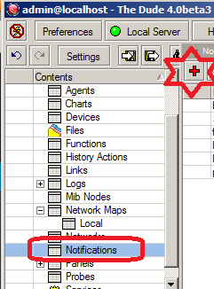
Now at DUDE Service, on the left menu, Goto Notifications and add new one by click on + sign or right click/add.

As showed in the image below . . .

add-notify

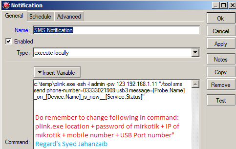
Now use following details.

Name = SMS Notification

Type = Execute on Server

Command:

c:\temp\plink.exe -ssh -l admin -pw 123 192.168.1.11 "/tool sms send phone-number=03333021909 usb3 message=[Probe.Name]_on_[Device.Name]_is_now__[Service.Status]"

or as mentioned by Tarquin Douglass ,

c:\plink.exe -ssh -l admin -pw 123 x.x.x.x "/tool sms send phone-number=12345678 usb3 message=\"[Probe.Name] on [Device.Name] is now [Service.Status]\""

[Change the password + IP + mobile number + USB Port number from above command]

Make sure your device name and message have no BLANK SPACES in it, thats why I used underscore or dash.
It took me 3-4 hours just to figure out that spaces were not supported or create problems with brackets [( )]
hope this will help some one

As showed in the image below . . .

sms-notify-image

.

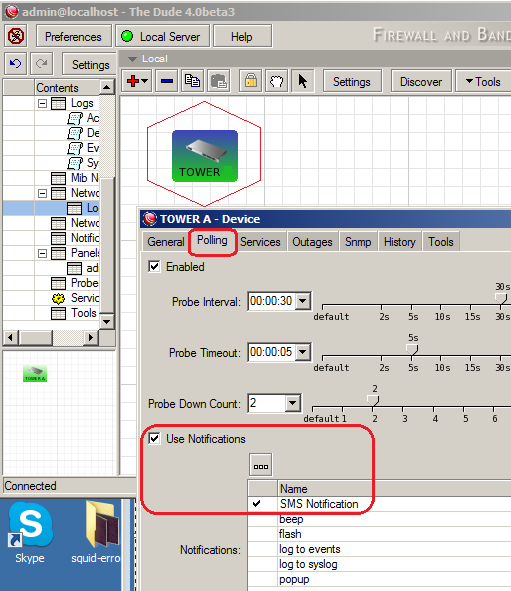
From your MAP, select the device you want to monitor and receive sms alert for.
Goto POLLING , and click on USE NOTIFICATION

Now you will “SMS NOTIFICATION” , Simply Select it, and click on APPLY/OK.
As showed in image below . . .


dude-monitor-target.

Now test it by disconnecting that target device (or for test change the IP address to some unreachable IP in target IP)
You should receive the alert on your SMS :). Do monitor the Mikrotik LOG window for the activities. also enable GSM debug so that you can aware of its activity.


2- Send SMS from Windows base DUDE using Linux Base KANNEL SMS Gateway [updated 10th Oct 2015]

Download WGET for windows from WGET  and Copy it in any folder of your choice. example c:\wget , you will get wget.exe in c:\wget\bin folder. Adjust it in dude notification command section accordingly…

Now in DUDE , Goto NOTIFICATIONS and add new notification as showed below …
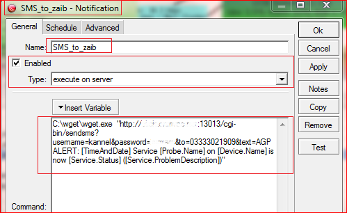
Name: SMS
Type: Execute on SERVER
[make sure you have copied the wget file into the appropriate folder or change the location as per requirement]
Command: C:\wget\wget.exe  “http://kannel_gw_ip:13013/cgi-bin/sendsms?username=kannel&password=kannel_password&to=03333021909&text=AGP ALERT: [TimeAndDate] Service [Probe.Name] on [Device.Name] is now [Service.Status] ([Service.ProblemDescription])”

Note: Change the kannel gateway ip address, kannel authentication data, and mobile number.

As showed in the image below …

notifi


Now add this SMS notification to any probe of your choice, like

notific-2

End result 😀

agp_alert


Regard’s
Syed Jahanzaib