This post is a quick reference notes for myself on how I managed to rectify some of long pending IT related issues which were left by previous network team, including AD Domain S.L.D migration to FQDN / Public IP scheme being used at Private LAN & its migration to multiple /24 Private IP Pools, Single default VLAN-1 migration to Different VLAN’s with smaller subnets.
The number of desktop/laptop/devices were in several hundreds. Downtime was not an option, therefore we managed to complete the task using parallel topologies for each segment.
Our existing network was running on default VLAN with /8 flat subnet, having each & every device on default VLAN-1 generating enormous number of broadcasts flooding causing network delays/timeout. There was no control on any switch segment, All switch edge port were set on Default roles making situation even worst from Spanning-Tree protocol flooding perspective. Above all like Cherry on the TOP, existing admin used public IP scheme with /8 subnet & many websites which were on this subnet over the internet, never worked on our network.
To over come these issues without any Downtime or disruption, I decided to sort issues on a one by one basis by creating parallel network, using below methods
SLD/FQDN Migration:
- On same network, I added new FQDN A.D Domain, Established two way trust between both domains. Then using Microsoft migration tool (ADMT ), I start migrating users (one by one, targeted activity ) from old SLD to FQDN. More details are documented in another article.
Short Notes for Active Directory SLD to FQDN Cross Forest Migration – Using ADMT tool
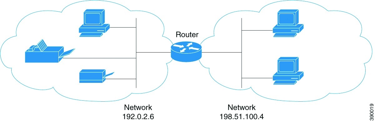
* Network Related *

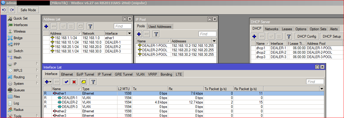
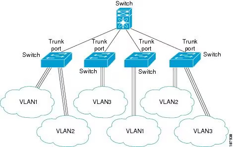
We have Cisco L3 Stacked switch at data center & all departmental L2 switches are connected via 10G Fiber TRUNK links. To convert the existing Public IP scheme to Private without having any downtime, I I designed different VLAN’s scheme with smaller /24 private IP’s pool on per department basis, Created there SVI’s on main core switch stack. Using IP helper commands. I also created different vlans for management example different vlan for switch / access points / devices / servers & Users. I created DHCP relay pointed towards our domain controller. As I have to create parallel environment to avoid any downtime or any communication disruption, I didn’t changed any server’s device IP, rather On all server’s I create routes using ROUTE cmd) pointing to switch gateway (SVI) so that all devices can two way communicate with each other either its public or private.
Segmentation of different VLAN’s
Slowly gradually, we changed the Server’s/users/devices VLAN form 1 to new vlan scheme, & changed the DNS entries as well (Most of them auto updated there DNS entries at DC DNS upon rebooting or using Group Policy to enforce DNS registration every 30 minutes). New vlan users were able to communicate with older vlan-1 or x users because we configured CLASSLESS for each DHCP pool pointing to Core switch gateway using there corresponding gateways (SVI’s IP’s at Core L3 Switch).
Some Common Tuning we performed resulted in increased reliability of overall network
- Most important set root bridge priority to 1 on L3 Core switch by setting the bridge priority to 1 then set all the others switches to higher number. This will ensure the STP is built correctly
- Subdivide the network into multiple VLAN’s & smaller logical subnets e.g. Servers, Users, Management vlans for switch n access points, devices like printers , time machines & NVR cameras, departmental vlans etc with each having a /24 e.g. 192.168.1.0/24, 192.168.2.0/24 and so on
- On your core switch allocate SVI’s per required vlan
- ensure each device can talk to each other using intervlan routing [exception to those who required firewalling/security]
- Make all trunk uplinks 802.1q trunks [doesnt requires at new cisco IOS]
- TAG / Associate ports on all switches with the appropriate vlans
- Ensure all ports roles are defined properly, example edge / trunk ports
- User connected EDGE port should be in access mode, & Portfast enabled along with BPDU enabled.
- Disable all UNUSED ports (or make default sandbox VLAN for all unused ports & assign those ports with this sandbox VLAN, to ensure that unknown devices inserted in those ports should remain in sandbox VLAN
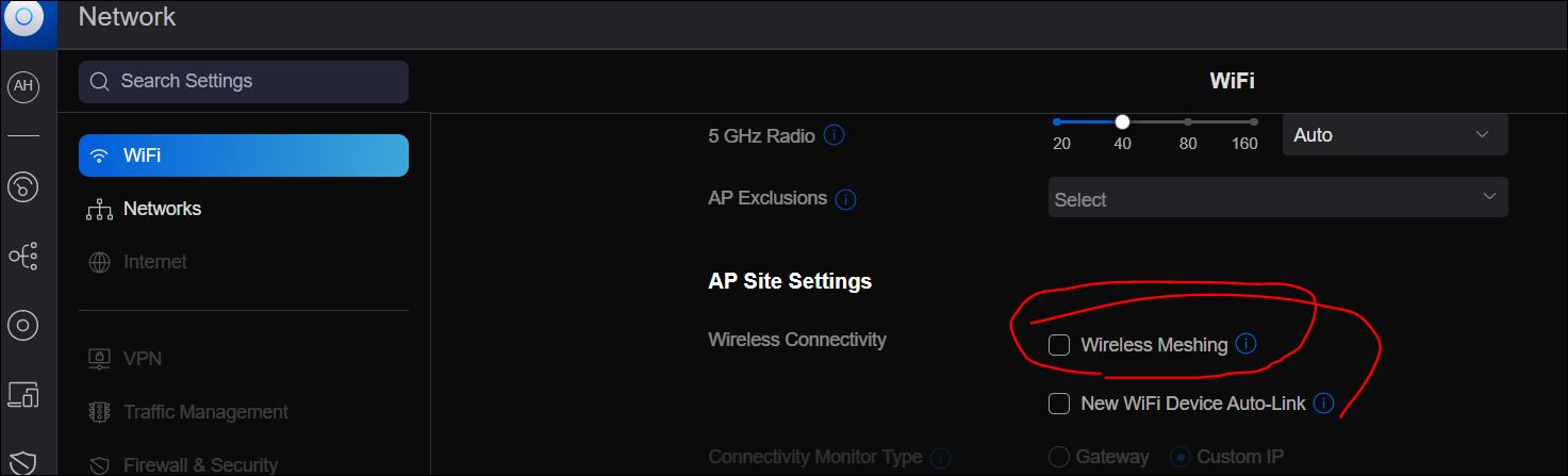
- Make sure your Wifi APs are not meshing or bridging
- I added all devices in DNS entries like printers etc , and at user end, added the required devices by DNS name, so that next time if any changes are required, modify the DNS entry only & no need to reconfigure the device at user end.
Some DRY theory on ACCESS/TRUNK Mode
- An access port can have only one VLAN configured on the interface; it can carry traffic for only one VLAN. An access port transmits packets on only one VLAN (traffic is not tagged on this type of port). Portfast feature causes a switch port to enter the spanning tree forwarding state immediately, bypassing the listening and learning states. Portfast on switch ports connected to a single workstation or server allows those devices to connect to the network immediately, instead of waiting for the port to transition from the listening and learning states to the forwarding state.
- Edge ports are configured such that they immediately go to the forwarding state. However, this does not mean that there is no loop protection. It is assumed that edge ports will connect to end devices, and thus it is convenient for them to go directly to the forwarding state. However, someone can try to plug in a switch on such a port and can try to become the root bridge or may connect to multiple ports and create a loop. That’s where you should use BPDUGuard. On all edge ports, BPDUGuard should be enabled so that as soon as such a port receives a BPDU, it will go into err-disabled state, thus preventing an L2 loop. Now keep in mind that for RSTP, if you don’t enable BPDUGuard, and a BPDU is received on an edge port, the edge port simply loses its edge port status.
Windows / Linux Route CMD’s for OS with Static IP

At user end, all routes were distributed via windows DHCP Classless routes which worked transparently fine. But server OS with static IP I had to provide proper routes according to our network. Example we have two gateways for internet at LAN, one is SANGFOR IAM for end users, second is Router/NGFW for server ends. Some times we have to route user/server at one or other gateway.
First get the Interface number via ROUTE PRINT CMD
-
route print
(Note down the interface name, example Interface number is 8)
Now add the appropriate gateway for intervlan routing & internet routing as well
*** WINDWOS OS / ADD PERMANENT ROUTES using ROUTE command
Note: -p syntax with route cmd adds the route on permanent basis (in registry)
# Below is an example for SERVER which is on 172.16.2.x VLAN , below is for INTERVLAN Routing for local subnet’s intervlan routing . 172.16.2.1 is the CORE Switch Gateway which have SVI’s configured,
route add -p 172.16.0.0 MASK 255.255.0.0 172.16.2.1 metric 1 IF 8
route add -p 192.168.0.0 MASK 255.255.0.0 172.16.2.1 metric 2 IF 8
# Below is for Internet access , 2 Gateways with priority pointing to Sangfor & NGFW Respectively (NGFW route is added as some port forwarding is done which is routed via NGFW)
route add -p 0.0.0.0 MASK 0.0.0.0 172.16.2.2 metric 3 IF 8
route add -p 0.0.0.0 MASK 0.0.0.0 172.16.2.6 metric 4 IF 8
*** LINUX / ADD PERMANENT ROUTES in interfaces FILE [Ubuntu ver 16 or below]
- For older version of Linux (Ubuntu ver 16 or below) I added below in interfaces file
up route add -net 172.16.0.0 netmask 255.255.0.0 gw 172.16.2.1
down route del -net 172.16.0.0 netmask 255.255.0.0 gw 172.16.2.1
up route add -net 192.168.0.0 netmask 255.255.0.0 gw 172.16.2.1
down route del -net 192.168.0.0.0 netmask 255.255.0.0 gw 172.16.2.1
- For new version of Ubuntu ver 18 & above, I used below [sample file shown below]
cat /etc/netplan/00-installer-config.yaml
network:
ethernets:
ens160:
dhcp4: false
addresses: [192.168.0.28/24]
nameservers:
# DNS server is on different VLAN
addresses: [192.168.1.71,192.168.1.72,8.8.8.8]

# STATIC ROUTES for INTERVLAN ROUTING, GW pointing to L3 Core Switch corresponding SVI
routes:
- to: 10.11.0.0/16
via: 192.168.0.1
- to: 10.10.0.0/16
via: 192.168.0.1
# FOR INTERNET , GW POINTING TO SANGFORIAM OR NGFW
- to: default
via: 192.168.0.6
version: 2
DHCP for Different VLAN Users


On Domain controller (Default route pointed towards L3 Core Switch SVI) I created multiple IP pool for corresponding VLAN users. At departmental L2 switches, I added corresponding VLAN’s & with the help of IP Helper at core switch, users get IP from the Domain controller DHCP server via there corresponding vlan pool. One by One all departments moved to different Vlan’s with smaller IP pool resulting in dramatically decline in broadcast traffic. This improve network connectivity reliability at a greater extent.
IP Helper not working across VLAN’s

I got stucked at one point where ‘IP helper’ was not forwarding the other vlans (like vlan 10/11/12) users dhcp pkts to domain controller dhcp residing on default vlan-1 despite all settings seems correct, I contacted few Cisco / VM experts & they remotely checked in cisco & vm config in details & yet no one was able to solved it. At Core switch there was this “no service dhcp” set & it was the culprit , as soon as I set it to service dhcp, & Alhamodlillah! all got sorted !
One example of IP helper at Wireless (with mDNS support) VLAN interface on L3 Core Switch
interface VlanXX
description WIFI_XXX-MOBILE-VLAN
ip address 10.0.0.1 255.255.255.0
ip helper-address 192.168.0.1
service-routing mdns-sd
service-policy-query querier 60
service-policy mypermit-all IN
service-policy mypermit-all OUT
VLAN’s in VMWARE ESXI

Configuring VLAN’s in ESXI was easiest part. The only thing at switch level was to configure TRUNK at which ESXI is connected to. On esxi server, I created new network (VLAN) & tag the required vlan to desired VM guest & Done.
Allah Shuker!


Ref:
Howto Add VLAN in ESXI Server
Following is quick short notes on howto add VLAN in ESXI Server
- Login to ESXI (I am using VCSA to manage all esxi servers).
- Now Goto Configure
- Networking > Virtual Switches (NEXT)
- Add Networking (NEXT)
- Select ‘Virtual Machine Port Group for a Standard Switch’ (NEXT)
- Select ‘Select an existing standard switch’ & click on BROWSE & select vSWITCH0 (NEXT)
- In next window (Connection settings) at NETWORK LABEL , type suitable name like VLAN-100 / & under VLAN ID tab, type in the required VLAN ID example 100 (NEXT)
- Click on (FINISH).
Done. Now you can assign this vlan to your desired VM Guest in its network adapter settings.
UniFi Access Points with Multiple SSID’s & VLANS


We have many wireless access points installed at various locations & all controlled centrally by UniFi controller software application. After addition of VLAN’s we decided to remove the default vlan1 SSID, & introduce new SSID based on targeted audience like XYZ-Corporate , XYZ-Mobile , XYZ-Guest & each SSID is tagged with different VLAN’s to control the users based on SSID type. The setup was straight forward. First We create separate VLAN for access points management e.g: VLAN100 & at all access points we changed the ips with vlan100 pool & set there default gateway to vlan-100 SVI configured ta Core Switch, Also we changed there management VLAN to VLAN-100.
- Sample of IP/MGT VLAN setting on per AP Basis

- Adding new VLAN ID in UniFi Controller Application
To add VLAN in UniFi Controller ,
Goto SETTINGS > NETWORKS > & create new VLAN with VLAN-ID number,

- Adding new SSID in UniFi Controller Application
Now to ADD SSID in UniFi Controller Application& tag with NEW VLAN-ID,
Goto SETTINGS > WiFi > Create NEW Wifi , Now enter the name of SSID like XYZ-Corporate & in Network select the desired VLAN you created in earlier step

Warning: After applying any setting that needs to be synced to all access points in the group, traffic disruption & timeout to access points may occur upto 1or 2 minutes. Therefore perform such operations Only in Off-Peak hours.
UniFi Access Point – Trunk Port Config at Cisco Switch PORT

At Cisco switch where access points ethernet cable is attached. We did below config for that port,
interface GigabitEthernet1/0/20
description UniFi_AP_Finance
switchport mode trunk
This enabled to carry all vlans including AP Mgt / Different Vlan’s based on various SSID’s [each SSID tagged with different VLAN via Unifi Controller application]
UniFi Wireless Meshing Causing Loop/Broadcast

We noticed that whenever we modify any settings which requires syncing with All AP’s, then one by one AP’s freezes packet transmission connectivity & then get back online few 15-20 seconds but few access points uplink gets there uplink connectivity with another AP wireless (Meshing). This was also creating the loop broadcast. Disabling WIRELESS MESHING in Unifi Controller application & then readopting the AP’s reduced such events.
SANGFOR VLAN
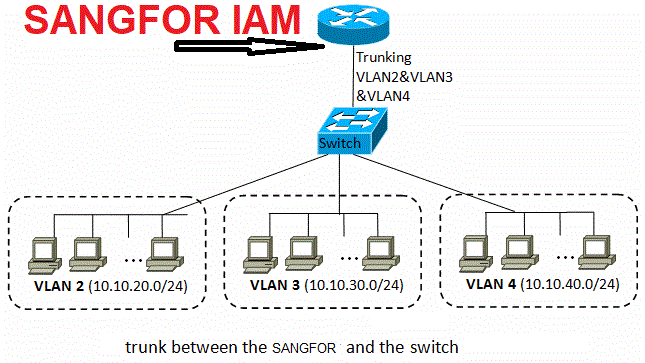
To Provide internet access via sangfor to all vlan users, we added corresponding VLAN’s in SANGFOR IAM device, Each vlan sub-interface with corresponding IP to be used as gateway at corresponding VLAN users (all via DC DHCP)
To add corresponding VLAN’s in SANGFOR,
Goto System > Network / Deployment / Settings > & under LAN interface Page add as per below
10/10.10.10.3/255.255.255.0
Whereas 10/ is the cisco VLAN number, and then the IP of this sub interface & then the subnet
Warning: After modifying any network related settings, SANGFOR Network services will be restarted, & may cause traffic disruption, therefore perform such actions in off-peak hours.
TIPS:
Bonjour (mDNS) discovery across different VLAN’s (Wired/WiFi)
After segregated network into smaller subnets along with separate vlans for wired/wifi users/devices etc, users were not able to *cast/discover* LCD TV / MFD Printers if both are on different vlans. (they works fine if the device & user are on same vlan/subnet). If wired user on vlan2 tries to connect with LCD (on wifi) on vlan3, he cannot. if they are on same vlan they can connect fine. This is because broadcast doesnt’ works across different vlan.
In UniFi Controller, there is an option of enabling mDNS which is a service provided by a Unifi router like USG, UXG Pro or UDM. but since we didn’t had any UniFi router/switch therefore UniFi mDNS didn’t had any mDNS functionality and it didn’t worked. We had to configure the service to repeat broadcasts across VLANs using Cisco switches.
The solution was to enable the mDNS ‘service discovery’ at Core L3 Switch.
At core switch where all SVI’s are configured, I allowed mDNS service on particular VLAN’s (wired/wifi) using below CMD’s & the problem got sorted out.
interface VlanXX
description WIFI_MOBILE-VLAN
ip address X.X.X.X 255.X.X.X
ip helper-address X.X.X.X
service-routing mdns-sd
service-policy-query querier 60
service-policy mypermit-all IN
service-policy mypermit-all OUT
end
I will keep updating this article as I get free time
Regards
Syed Jahanzaib